ANALYSIS
Description of Analyses
The analyses of the foundry flask punch out focuses mainly on the force that is required to “punch out” the compacted foundry sands from current flask sizes. The maximum force for punching out foundry sands from different flask sizes was achieved by placing molds, compacted to 125 psi with a jolt squeeze molder, on a hydraulic press with a 3000lb load cell under the piston. From these tests the maximum force needed was acquired. By factoring in different scenarios it seemed antique to design the machine for a 2000 lb. max load on the flasks. From this test the arbor press is able to be sized appropriately so the user does not have to apply more than 100 lbf. to press the sands out from the mold. The reaction forces on the machine will take ample engineering work to find and define the support system for this operation. These support system includes but is not limited to the rails supporting the flask, the column supporting the arbor press, the arbor press shear head, and the general framework of the machine.
Analysis
The analysis for the machine started with finding the size of a punch head that would be able to go through all flask sizes that the machine will be capable of handling. Finding the size of the punch out head determined the shear area of the sand that will be punched out of each flask. Research shows that the approximate shear area for the green sand would produce a maximum required shear load of 1,500 lbs. From this analysis the machine was analyzed for a maximum load of 2000lbf.
The calculated parameter of a maximum load of 2000 lb. leads to most of the deflection calculations that were done in this project. A large area of analysis in this project revolves around the support column that holds a column mounted arbor press (drawing in appendix B-1) above flasks that are loaded onto angle iron rails. In appendix A-1: A-4 parameters for the column and deflection requirements area addressed.
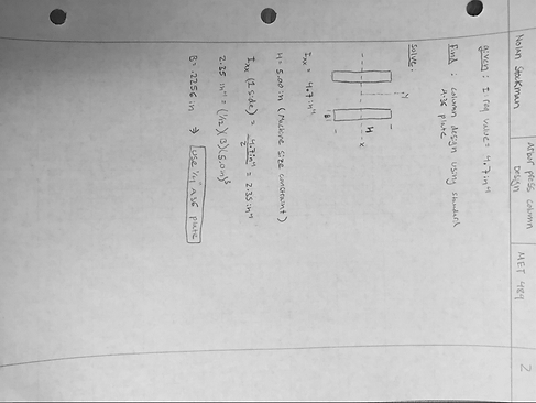
In Appendix A-1 a ridged deflection requirement of 1/64” was established for the support column that holds the arbor press above the loaded foundry flask. The 2000 lb. force was converted into a moment at the end of a cantilever beam. This method of analysis seemed appropriated due to the comparative thickness and rigidity of both the arbor press and the extended section at the top of the beam. The deflection that is unaccounted for in these sections will be negligible when compared to that of the long portion of the column. The deflection requirement will be measured 16 ¼” from the columns base plate due to that being the length that is perpendicular to the axis of rotation that the arbor press will produce a moment about. By analyzing the beam as a cantilever beam with a moment on its end it was found that a moment of inertia about its bending axis must be 4.7 in^4 to produce a 1/64” deflection when made from A-36 steel plate.
Appendix A-2 shows the design of the column about its bending axis. This design was made to produce a moment of inertia value of 4.7 in^4 with respect to this axis. The column design was established to be made from two plates separated by the distance needed to mount the arbor press correctly. By constraining the height of the beam (with respect to the bending axis) to 5 inches, due to the overall space available to the machine, the base thickness was able to be solved for. The solution held a desired base thickness of .2256 inches. This value was rounded to .25 inches so common ¼” A-36 plate could be used for construction. Appendix A-3 re-analyzes the findings from Appendix A-1 with an established beam shape so the actual theoretical deflection could be calculated and tested against at a later date. A-3 establishes that the deflection will yield .014” when the arbor pressed is loaded to 2000 lb. This deflection is less than the 1/64” deflection requirement by approximately .0016”.
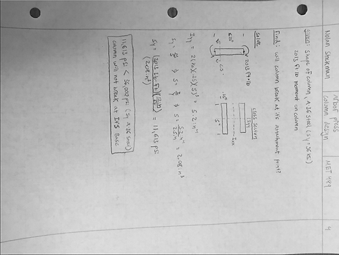
Appendix A-4 & A-5 analyze is the column and its welding to the base will be able to withstand the same moment that the beam was analyzed for deflection. Appendix A-4 shows that at the beam base there will be a stress of approximately 11,600 psi at the face furthest from the bending axis on both ¼” plates. The 11,600 psi bending stress is less than the 36 ksi yield value for A-36 steel. This establishes that the column will not break when the arbor press is loaded to 2000 lb. Appendix A-5 analyses the same principle as A-4 with respect to the welds that hold the column to the column baseplate. The column will be welded to the baseplate with 7018 welding rod which has an ultimate tensile strength of 70,000 psi. To ensure the welds will hold during loading a minimum weld width was calculated from the minimum moment of inertia value with respect to the bending axis. By welding along both sides of both plates in the column a weld width of .0207” will produce a bending stress of 70,000 psi at the weld furthest from the bending axis. A single pass weld will produce a weld thickness larger than .0207”. This establishes that the designed weld plan for the column is sufficient.
The requirement to remove 90% of foundry sands from the flask. To do this a punch head of 9”x 9” was created with an inverse tetra pyramidal structure to concentrate the shear force as the punch head comes into contract with the compacted foundry sands. This head will be attached to the arbor press with a clevis pin. Appendix A-6 evaluates the size of the pin in order to withstand a 2000 lb. load by the arbor press. By making the pin from 316 stainless steel the pin size was determined to be 3/8” with a X1.5 factor of safety applied to it.
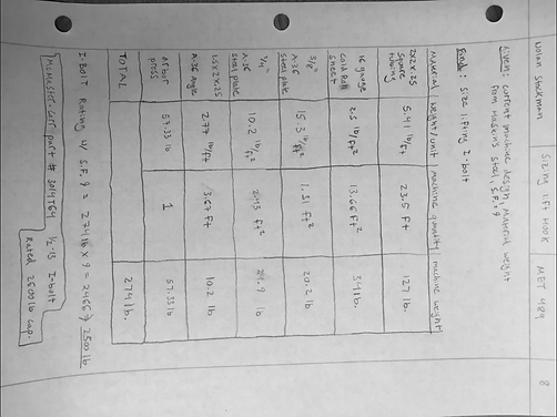
In this design most of the members will be welded in place. Only the arbor press and the 16 gauge sheet metal basket will be bolted onto the design. The torque values for the grade 5 bolts that will be used is found in Appendix A-7. In addition a bolt on ½-13 thread I-bolt will be placed at the top of the machine directly over the machines center of mass. This will fulfill the requirement of the machine being able to be easily moveable. The sizing calculation for this I-bolt can be found in Appendix A-8.
To fulfill the requirement ergonomic flask loading and unloading angle iron guide rails were used to direct flasks below the modified arbor press when the user loads a flask from the machines side. Appendix A-9 shows the required deflection of less than 1/8” when an 18” x 12” flask is loaded to 2000 lb. By using 2” x 1.5” x ¼” angle iron and calculating the moment of inertia about the 2” flange the deflection was calculated to be .11” which is less than 1/8” by .015”.
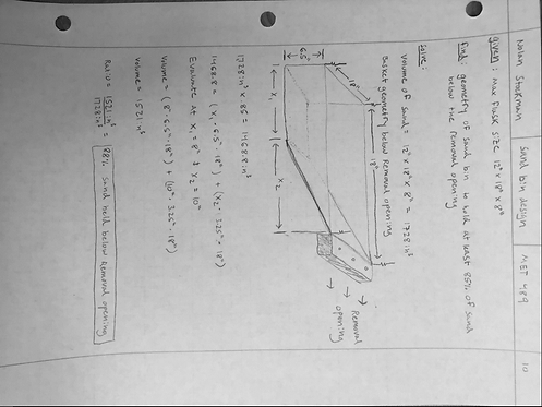
This design has a requirement that when the sand and casting are removed from the flask that they are transferred into a container that allows for easy removal. To account for this a sand collection bin will be made according to the specifications calculated in Appendix A-10. These specifications are produced from the desire to hold 85% of the sand volume from the largest flask size below the extraction point. A tapper was added to the collection bin from the removal point to allow for a standard flat nose shovel to be used to remove the foundry sands from the collection bin.
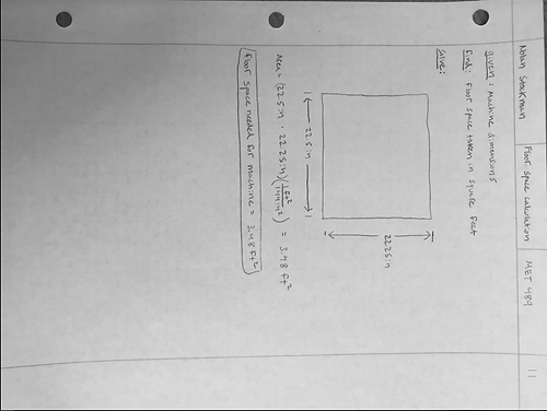
The placement of this machine will be near sand elevator. In this area there is limited space and it is important to ensure that machine will be able to fit in the required area. Appendix A-11 calculates the footprint the machine will use. This information will be used in the planning of the placement of the machine.
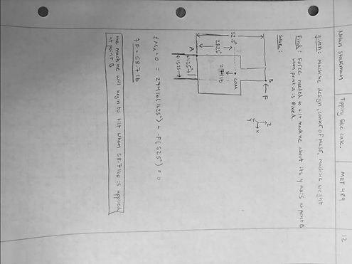
Lastly it is important that the machine does not tip easily. The tilting force was calculated in Appendix A-12 to see what the estimated tilting force is when applied at the highest point on the machine. This force was found to be 58.7 lb. when applied at the top of the column in respect to the machines Y axis. This calculation ensures that the machine will not be tipped accidently from any side loading. The machine utilizes 2”x2”x1/4” for its frame. The use of this relatively heavy material lowers the center of mass on the machine and makes the machine less likely to tilt from a unintended side load.